Describe How You Handle Sending / Receiving Data Over Bluetooth
The code to send and receive data over bluetooth remained the same as in the prior lab. The only thing that
changed was that the array used to store ToF information was instead used to store Yaw information which corresponded to my theta.
Code Snippets
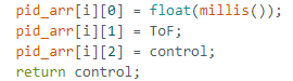
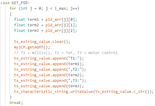
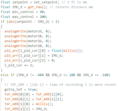
As can be seen, since I repurposed my code. I now pass in the yaw data IMU_d as ToF into PID_control.
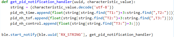
Therefore, yaw data is saved into a pid_arr where ToF data was saved in Lab 5 and then the case GET_PID send it to
the notification handler written on the python side which then can get the information.
I repurposed my code in this scenario
since it was unnecessary to rewrite the function entirely.
However, in future labs if both are needed at once it should be fairly simple to
implement extra memory in the array to save either IMU data or ToF data depending on the case
and therefore run both of them.
.
Lab Tasks
P/I/D Discussion / Input Signal
I ended up choosing to implement PI control over PID control since adding the
derivative term amplifies the impact of noise on the controller and PI on its own showed sufficient performance. I first set all values to 0
except for KP which I started at .06 which was my value from the last lab and began debugging it.
I chose not to do basic digital integration similar to what we did in Lab 2 due to the following problems:
Digital integration involves accumulatiing error over time causing a drift
in yaw. Therefore, using this technique would result in worse performance of PID_control over time as drift accumulates.
Therefore, for the the PID input signal I decided to use the digital motion processor (DMP) to minimize the yaw drift
since using a complimentary filter similar to Lab 2 with just yaw measurements wouldn't work
since there are no accelerometer yaw readings and other filters (such as Low Pass Filter) would still lead to drift over periods of time.
Therefore, I figured it would be easier to use the DMP which uses the data from the accelerometer, gyroscope,
and magnetometer to accurately get yaw without drift.
To implement the DMP, I took inspiration
from the example shared in class and the example code the tutorial suggested we use.
Code changes are shared below.
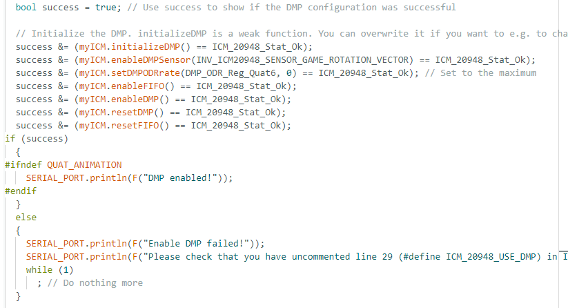
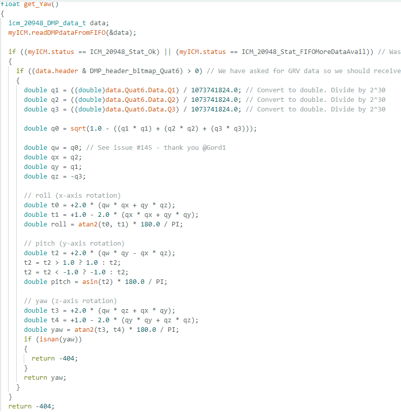
As one can see, I added to the setup() to
initialize the DMP, then I implemented get_Yaw() to
output the yaw using the DMP using the data from its FIFO whenever it had
valid data available and output -404
whenever there were issues with getting the yaw thus filtering those measurements out.
Some limitations on the sensor to be aware about it that using the DMP mode
I did sets the maximum rotational velocirty to 2000 dps. This is sufficient for
our applications since we won't be moving our robot at a faster velocity. One could change the DMP mode to configure that parameter.
Derivative Term
So I implemented PI control as opposed to PID control so my derivative term was 0.
However, had I decided to tune for KD in theory changing the setpoint could lead to spikes
in the data called derivative kicks due to the sudden change in desired theta resulting in a high error.
As a result, this would result in spikes of motion unless you apply a lowpass filter to eliminate
any high variance in data.
Programming Implementation and Debugging
I could repeatedly receive new data via my notification handler
so long as I had space left in my arrays. Via debugging, I found my KP
to be .7 and my KI to be .001. I found my loop speed to be 11 ms.
However, get_Yaw() also returned yaw values at only a marginal slower rate.
Theoretically, it should be somewhat slower since it occasionally does return
invalid values that are filtered out but it was measured out to
producing a new valid yaw roughly every 11 ms as well. The range was between [-180, 180].
Some plots are shown below with various
measurements as I was debugging:
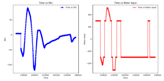
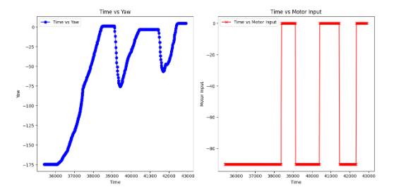
Plot 1: Controller still not working as desired due to prior code using -1 as an error output
since last code used that. Therefore, when it reached 0 it would spaz far in the negative direction.
Fixed by using -404 as my no value found output which was outside the range [-180, 180]
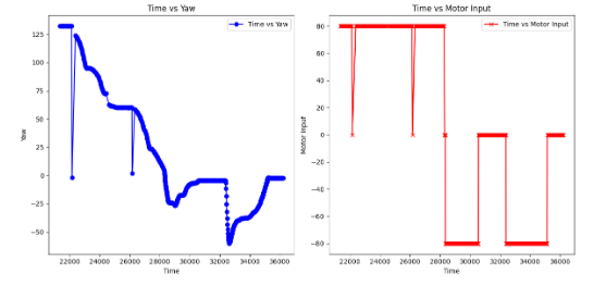
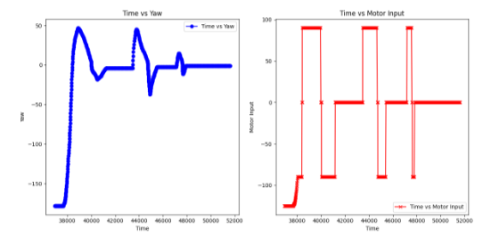
Plot 2: Controller is still having random irratic behavior. Issue
came out to be because of extrapolation from prior lab not working
as intended with yaw values. Was edited and fixed.
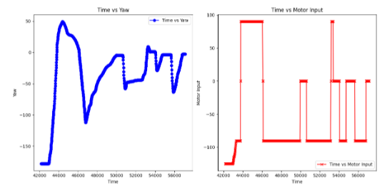
Plot 3: Plot of motion as seen in the later video after KI
implemented.
Plot 4: Some tweaks to values to allow for more variation in the
controllers motor input.
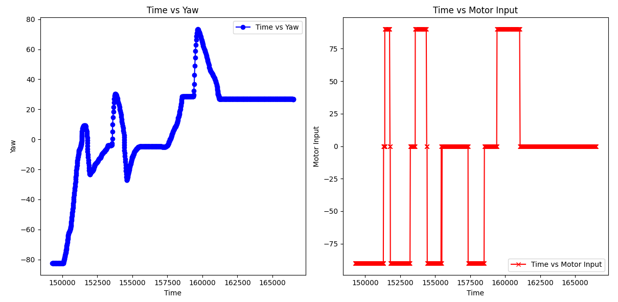
Plot 5: Plot of video with KI (windings implemented)
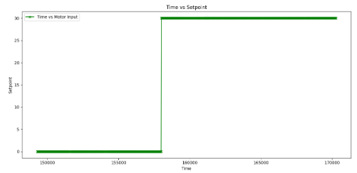
Setpoint Update
To update the setpoint I made a new case which could be called in python.
I then created a global variable set_setpoint which would be entered into the PID_control function
as set_setpoint and the case would update the value in set_setpoint. Snippet of the case
is below along with plot of change from 0 to 30 using ble.send_command(CMD.SET_SETPOINT, 30)
as well as it receiving taps and then moving back to the desired position.
There is a video next to it corresponding to the chart / situation. This code updates
it live since the ble.send_command allows for live communication over the bluetooth protocol
and the set_setpoint which is used as input is a global variable being updated in the case
via this command.
You will need to update the setpoint in real time in order to adjust
the navigation of the vehicle. However, theoretically,
if you were to make it fully autonomous you could write an
algorithm which chooses the setpoint just on the arduino rather than
waiting for a call over bluetooth.
In addition, some ideas in terms of how to control the orientation while the robot is
driving forward or back is to incrementally update the motor outputs
based on the initial orientation and final orientation resulting
in a curved path. Instead of having motors running in opposite directions,
one could just have one side be more powerful than the other.
An example of this would be if the vehicle were running straight
at 200, 200 (left & right wheel motor input respectively),
if one wanted it to move to the left then one could with the
appropriate computed time decrement it over time to reach values
of 150, 200 or whatever value was reasonable.
5000 Level
Wind Up Protection
Wind Up Protection is necessary in Lab 6 for the same reason
it was necessary in Lab 5. If you allow PID_I to build up with error over time
it will make your controller less responsive. Wind Up Protection, prevents this issue.
I just implemented it the same as in Lab 5 and the same value (250) worked. A video of it working
with windings and not without is under PI Controller Videos.
PI Controller Videos
Video 1: P controller working
Video 2: PI controller working (with windings)
Video 3: PI controller not working because windings missing