To send over bluetooth, I created a j * 3 array (where j is a value I could arbitrarily set depending on run time) which stored in the 0th index the time stamp, 1st index the ToF, and 2nd the motor input.
I just added to the array in the PID_control function. Below is a photo of the case called when I want to get the data on the computer.
To see how I saved the data into these arrays, one can reference the picture at the bottom of the lab report for the end function.
There was another case SET_PID which would trigger a flag that would begin the control loop.
On the python side I wrote a notification handler to receive the information in a similar style to prior labs.
Lab Tasks
PID implementation
I set my ranging distance to be long so that it could get more accurate measurements from further away.
Then since my motor input can be up to 255 and my ToF sensors would output distances up to 4000 since I use mm in my PID_control function.
I estimated my KP would need to be roughly 255 / 4000. This ended up being .06 and this KP ended up being a good value.
I ended up leaving the accuracy of my TOF sensor as is along with the programmable integration time..
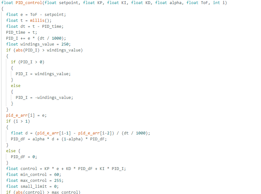
For PID_control, I used Dr Petersen's implementation referenced in the collaboration statement as inspiration.
This code uses as output for the control = KP * e + KD * PID_dF + KI * PID_I. KP, KD, and KI are constants which much be tuned.
e is the error, while PID_I and PID_dF is the error integral and error derivative respectively.
After implementing code for PID_control in C which can be referenced at the bottom, I parameter tuned in order KP, KI, KD and alpha.
I found the optimal values to be KP = .06, KI = .001, KD = .05 and alpha = 1.
Below are videos of them working started a bit over 2 meters away, with the first just having KP, the second with KP + KI, and the third with all values.
Extrapolation
After this I then looked for the frequency which my ToF sensor is returning new data.
This was by sending data over bluetooth only when a new ToF sensor data point was found. A graph can be seen below under
after the code snippet with ToF datapoints measured in blue.
I found this to be similar as to what I found in the last lab but with slight delays leading to it to be roughly 58 ms.
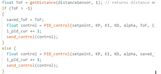
Then I updated my PID control loop so that it could constantly run PID_control.
For context, getDistance() returns -1 if there is no recorded measurement.
A code snippet can be seen below:
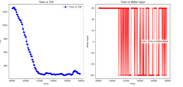
After this, I began implementing extrapolation. Using the red graph from the below section (instead of the blue as mentioned above) I determined how fast my PID control loop was running. I found it to be roughly
five times faster at 13 ms showing my PID control loop was working magnitudes faster than my ToF sensor rate.
Below is the graph of a run started relatively close to the wall so it slowly moved forward until it started oscillating.
This was used to measure the speed of getting new ToF measurements and also new motor inputs as described above.
Finishing Extrapolation
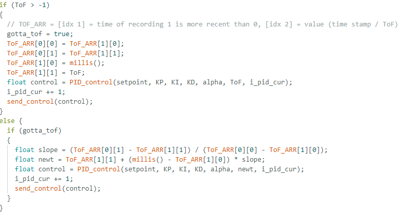
Then I updated my code to instead use the old ToF sensor data to estimate what the expected ToF sensor data would be.
The functionality involved doing as my new measurement to be prior_ToF + (current_time - prior_time) * slope
where slope = (old_measurement - prior_measurement) / (old_time - prior_time)
where prior is the last measured point and old is the measured point before that.
A code snippet can be seen below.
Here you can see ToF_ARR is used to store the last two time data points and the last two ToF sensor measurements.
So if a new ToF measurement is not received then it'll use the last two ToF measurements to pass into PID_control.
Windings
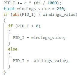
Lastly, windings is important to make sure that your PID_I doesn't get too large and cause your vehicle to slam into a wall due to accumulating error.
To test this, I changed my KI value to .01 to allow my PID_I value to increase at a faster rate.
Below you can see the video before and after I implement windings. The first video the car goes forward and crashes into the wall and keeps going while the second one doesn't crash.
A code snippet of my implementation of windings in PID_control function is below.
I ended up settling on 250 since 50 was too small of a value in my tests.
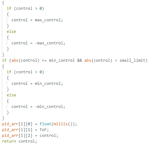
In the end, after putting together windings my PID_control function looked like this:
.
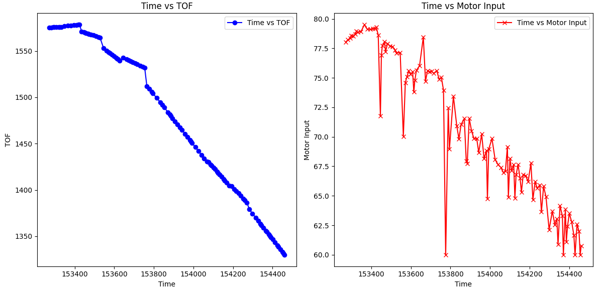
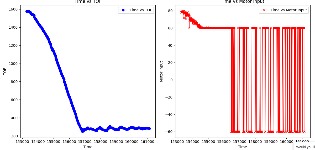
Here's a graph of my ToF and Motor Input for a run I did where as the ToF approaches the desired endpoint the control_input decreases.
The first graph is zoomed in on the decrease, while the second one includes the oscillations.