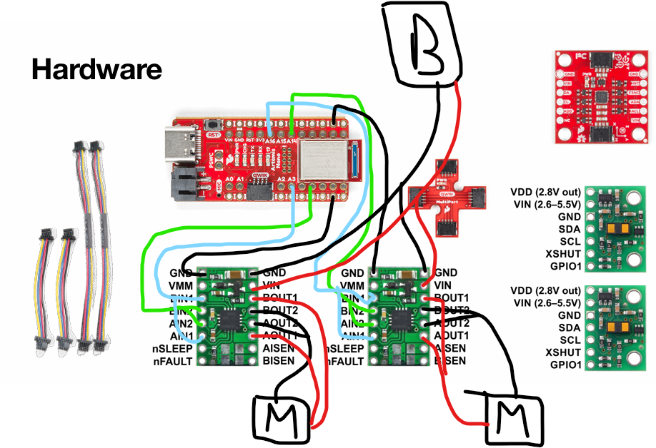
The following is my connections between the motor drivers, Artemis, and Battery. The pins I used on my artemis were A5, A3, A14, and A16 respectively.
Using any pins that did not involve A, still had the oscilloscope measuring output, but did not have the motors moving as anticipated.
I chose to use two pins on either side of the Artemis so I could easily tell which two associated with the same driver.
I ended up stripping my wires pretty short so that it could all fit in the car. My initial longer wires were unnecessary and added to issues when arranging things in the car.
For colors I chose green and blue for the in side, black for ground, red for power, and then the motors came with red and black wires so I just connected them to other red and black wires.
There are two reasons we would want to power the Artemis and motor drivers from different sources.
The main one is because the motors could pull too much power and cause the microcontroller to go out of its operational voltage range.
The other one is because if we want to flash the Artemis but it also powers the motor drivers then the motor drivers will cause the wheels to react to the prior code while we are working on the Artemis.
Lab Tasks
Setting Up the Car
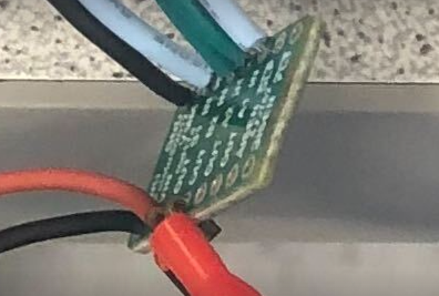
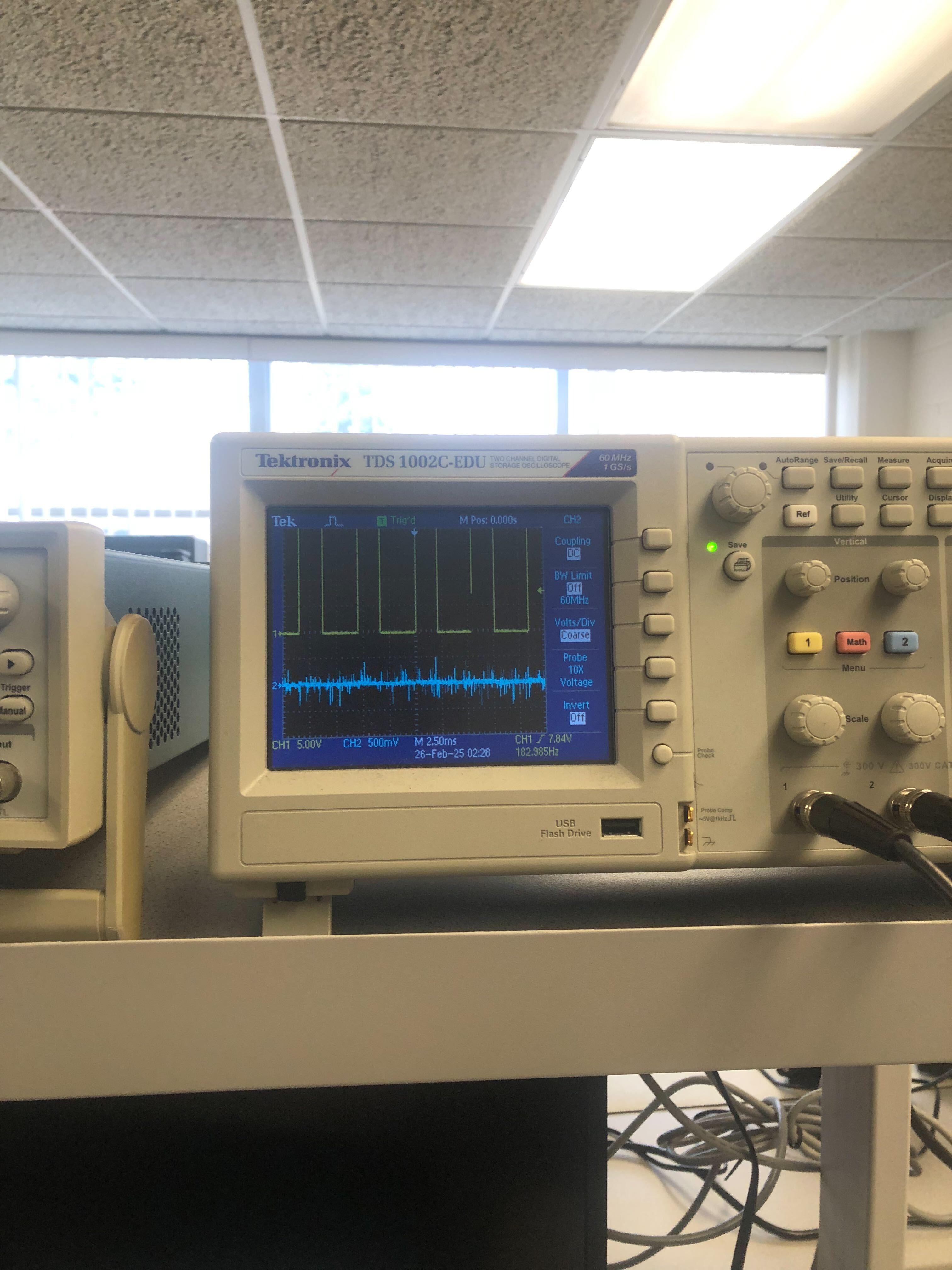
First, I connected to the power supply and used 3.7V and 1.5A and hooked it up with power connected to the outgoing red and black wire and the oscilloscope hooked up as seen below:
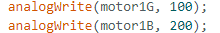
My oscilloscope output and the code used to test motor drivers are shared below
.
Next, I took my car apart and hooked up the motors to the motor drivers.
Below you can see videos of three of the tests I conducted.
The first one is motor driver one moving as expected.
The second one is motor driver two moving in direction 1 at a slow speed.
The third one is motor driver two moving in direction 2 at a fast speed.
These are just three of the tests I conducted. But across both motor drivers, I checked for both directions and checked that speed changes were appropriate.
After I plugged the motor drivers into my battery and ran it in the hallway with a timer.
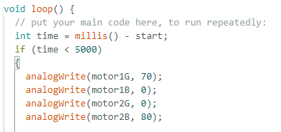
Below is a snippet of the code to how I implemented the time so it stops after 5s and a video of both wheels having it move down the hall.
.
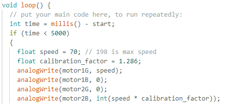
Then I implemented a calibration factor and I found it to be 1.286 greater for the second motor driver.
As a result, I implemented the following code and share the below video of it moving 6 tiles on a straight line.
.
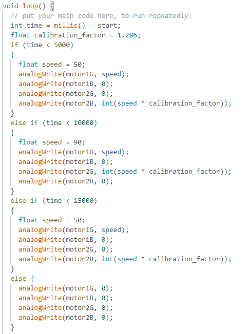
Then I implemented open loop movement which involved my car moving forward, spinning in place, and then going forward again.
.
Lower PWM limits
After repeated testing I was able to get the robot to start moving forward at a speed value of 35.
However, to keep it running, I wasn't able to lower it much more than that and only got it down to 30.
To test this I just had the robot moving at start speed for 5 seconds before dropping it down to a lower speed.
Analog Frequency
I found the analog frequency to be 190 Hz. This is adequately fast for the motors.
A benefit to manually configuring the timers to generate a faster PWM signal, is if we wanted to have
smoother motions at lower PWM frequencies.
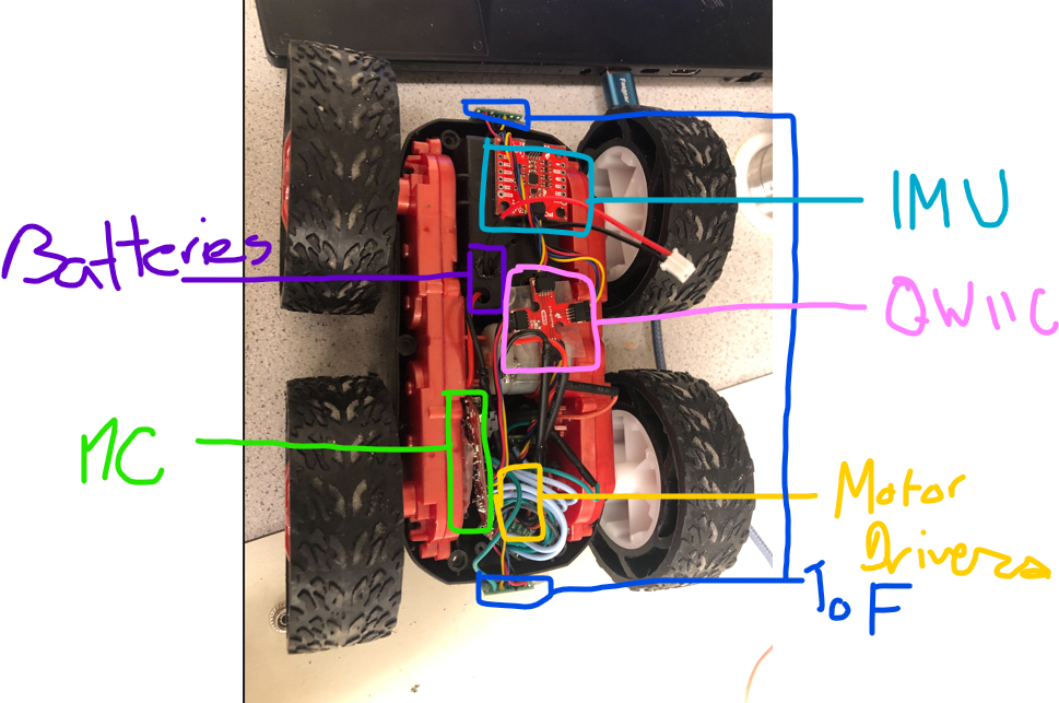
Final Car Config
Here is the final setup for the car. The Microcontroller isn't plugged in to the battery in the photo
and the batteries are located under the car but their wires heading up through the holes are circled.
Everything else is visible.