Per the documentation, I found the address to be 0x52.
I plan to power up the first sensor programmatically and update its address. This will then allow me to use the addresses of the sensors to individually address them without power cycling through the two of them.
I plan to place one sensor on the front and on the side. This allows me to have some level of data on both relative axis'.
There will be a lot of blind spots given this however.
Effectively, every other angle will be missed. So objects that are on the other side of the robot, behind the robot, or in the region between the front angle and side angle will be missed unless logged sometime earlier.
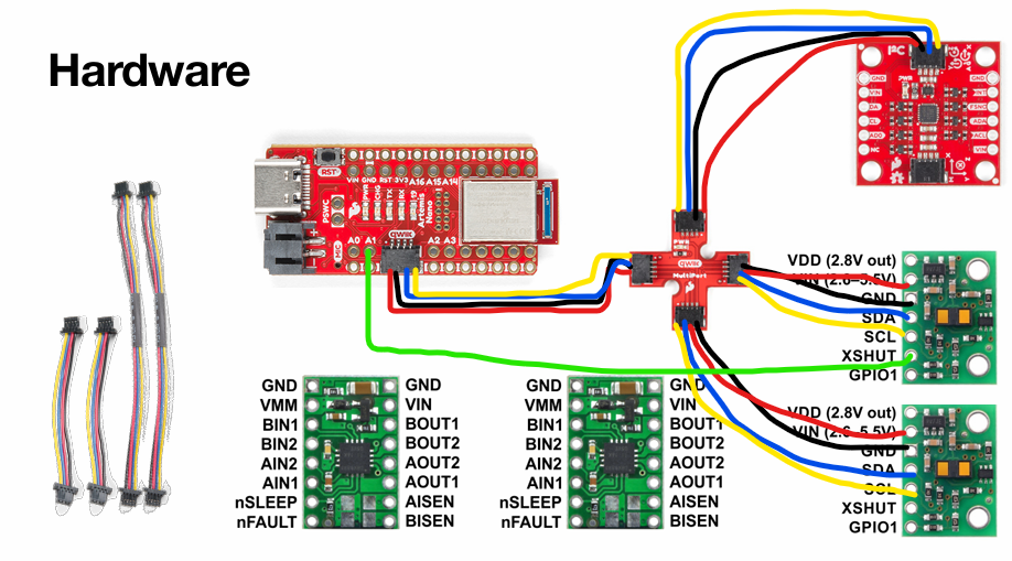
Used longer wires for the ToF sensors for more flexibility and shorter ones for microcontroller and IMU.
Mounted wires from behind to allow wiring to easily come out of car and have sensor pointed outward.
Lab Tasks
Getting To Work
First, I set up the battery. I ensured I was not one of the people who short-circuited it by cutting, soldering, & protecting the wires one at a time.
A picture of the battery connected to the microcontroller is shown below. In addition, you can see the ToF sensor connected to the QWIIC breakout board.
After cutting and soldering the ToF wires such that the blue wire corresponds to SDA and yellow to SCL,
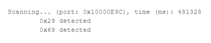
I then opened the Example1_wire_I2C code. I ran the code with the IMU and one ToF sensor attached and saw the following:
The 0x29 corresponds with the ToF sensor address. This is different than the anticipated 0x52.
This is because 0x29 is 0x52 bitshifted.
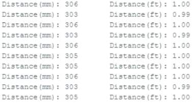
I chose the .setDistanceModeShort() because the maze will likely have tight quarters.
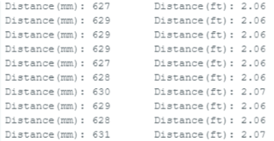
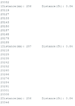
Attached is a photo of the outputs at one foot, two feet, and three feet respectively.
..
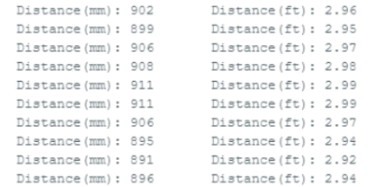
By slowly increasing the sensor, I found the sensor range to be roughly 3.7 feet. The highest logged value was 3.74. The accuracy of the sensor was consistently between +/- 0.1 feet.
Highest accuracy being at one foot. To test repeatability, I tested at two feet at several different times and consistently found it to be between .1 below and .1 above the target distance.
For ranging time, I printed the time in millis to the Serial Monitor when ranging time started and when the the
checkForDataReady found data. I found the time difference to be generally around 50 ms though there could be a lag in the Serial.println or the range could impact it.
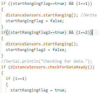
After this I hooked up both sensors simulataneously and wrote code to ensure that my code executed quickly.
To ensure quick execution of my code by not hanging up waiting for sensor data I set flags to note when to start ranging
and whenever the data is received it will then print out the data for the respective sensor.
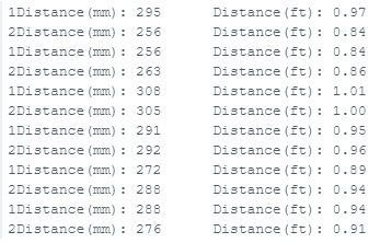
Below is a code snipet of checking when to start ranging and the output including both sensors working
and printing in parallel with and without millis() being printed.
..
As seen above, I found the loop speed with it being printed out to vary around 7-8 ms but a limiting factor / slowdown could be the result of repeated print statements.
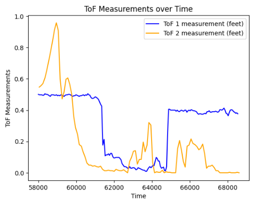
Then I sent over time-stamped ToF and IMU data to my computer.
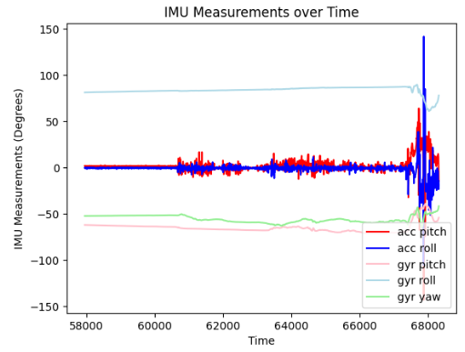
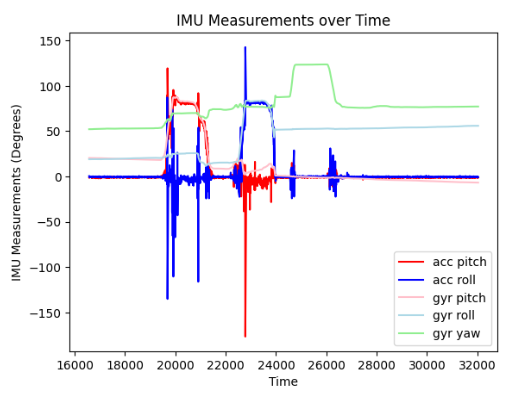
Below are a series of plots. The first is ToF data, the second is IMU data at the same time ToF data was captured. The third is IMU data but at another time but shown with more deliberate movements.
..
5000 Level
Per [1], Thermal IR and Traditional IR differ in the sense that Thermal IR
utilizes heat signatures to detect temperature variations. This is why
it is often used in applications such as for medical diagnosis' and night vision.
Traditional IR on the otherhand uses electronic sensors to detect IR radiation.
It is used more for communication and control devices.
In addition, according to [2] if we breakdown IR sensors we also find
Passive Infrared Sensors, Active IR Sensors, and Reflective IR.
Reflective IR sensors are good in very small ranges but lose effectiveness
with range. They are very energy efficient though and work by emitting IR and measuring
the amount reflected back.
Passive IR detects change in IR radiation so are good for detecting motion
but a drawback is that it doesn't perform well when for non-stationary tasks.
Active IR is the opposite and is used for obstacle detection since it operates
via emitting IR and detecting the reflection.
Lastly, to check the ToF sensor sensitivity to color and texture I did the following:
For color I tested the colors white, black, blue, and beige and found high accuracy for all four colors.
However, for texture I found uneven non-smooth textures to highly diminish the accuracy of the sensor.
For instance, rounded textures would cause the sensor misread the distance by a significant margin.
For instance, registering an object a foot away at .85 feet away.
As a result, I found the ToF sensor to be sensitive to texture but not color.