In order to maintain a more accurate robot, I decided that using
localization was paramount to being successful in this lab.
In lab 11, I had a ton of issues with getting localization working
because of a windows specific error that didn't occur when I borrowed
my friend's Mac. Unfortunately, I didn't have access to my friend's
Mac for this lab so I had to resolve that issue. Some other
people who came across the same bug determined that it was as a
result of conda environment configurations and opted to completely
remove conda from their system. Unfortunately, that wasn't an
option for me since I regularly use conda to handle environments
for several projects I worked on. Instead, I just decided to restart
and create a new system environment from scratch and make sure
all the pointers in the environment were proper and pointing
within the environment as intended and not referencing
any outside files. After going through
all that, I was fortunate to eventually get it to work on my
system, despite not having done anything significantly different
than my initial setup. I named this new environment FastRobots_ble_win
to differentiate it from the original environment I had and my
mac environment.
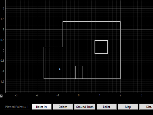
With all that out of the way, I then tested out localization on
the computer just to make sure my robot was working properly.
Results of my test run can be seen below.
Belief: (-.014, -.914, 10) Bel_index prob = 1.0
Path Planning
Given my localization was working fine on my
Windows computer that meant that I wanted to use that to
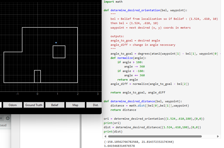
plan my route to the next waypoint. As a result, I implemented
the following two functions that would take in the belief and
the next desired waypoint. The first function:
determine_desired_orientation would output a value that would
be the amount the vehicle would want to rotate to move.
The second function: determine_desired_distance would
output the amount the vehicle would need to travel to reach its waypoint.
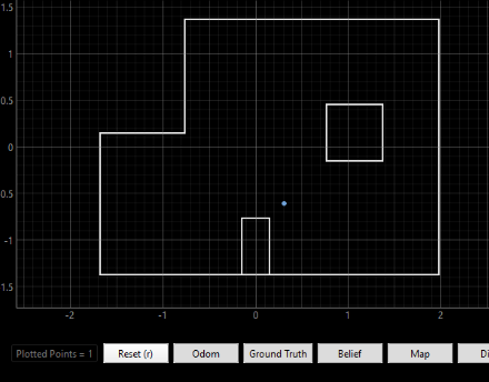
In the below screen, one can see a test localization and belief,
and it being input into both of these functions and the output orientation
and distances in degrees and meters seen as 21.8 degrees and 1.64 meters.
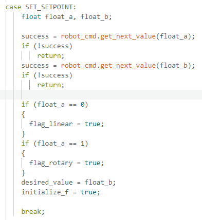
After getting these values I then repurposed my set_setpoint
function to take in two floats. The first float corresponded with
whether I wanted to rotate or move forward and the second float
corresponded with the values I wanted to pass to the linear
or rotary function. So for instance, if I wanted to use
orientation PID control, I could pass 1|45 to rotate 45 degrees.
This case is shared below.
Motion Control
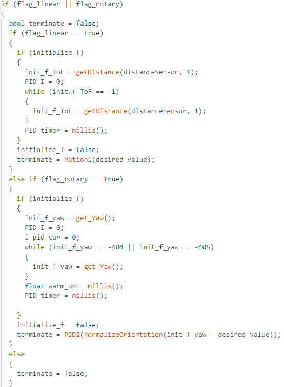
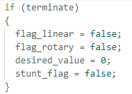
After these flags are set, in the main loop it executes the following:
First, it checks that the flags are true and sets terminate to false,
it will then on its first run go into the initialize_f block of
the respective linear or rotary section. initialize_f was set to
true in the case and it is set back to false after one run
through this block. This section is used to set variables back to
their initial condition, to get the current status of the robot,
and then to determine the desired conditions. For instance,
in the rotary case, it will keep running until a value yaw
value is returned and then the desired yaw is computed by taking
that value - the desired change and it will run the PID2 function
repeatedly until it returns true. In terms of the linear,
multiple different tactics were implemented. Motion1() just being one
of them. Motion1() takes in a desired time to move at a set speed
and it will repeat it until roughly in the range of the desired
target. However, a linear PID controller was also implemented there
although that faced some difficulties at certain points to get
precise measurements. All the functions that are set to = terminate
are used to determine and then send control to the car and are
used to return true if reaching the desired condition, and false it changes
are necessary.
When terminate is finally set, all the flags are set back to their
original condition to permit recalling it.
For details on the Linear PID controller reference Lab5 and for details on the
Orientation Controller reference Lab6. The Motion1 implementation, just takes in
a time to move the vehicle forward and checks that its within range.
Final Decisions In Terms of Control Functionality
I had a ton of issues with getting my orientation control to work perfectly.
I switched out IMUs, I made sure the expected values were printing out as expected,
I tried changing settings for the DMP but I was not able to get consistent results
for my orientation control. For some reason I couldn't get my DMP to output the values
that were necessary to reflect the real world circumstances. After talking with many TAs
and none of them able to pinpoint the issue, I decided to repurpose how my localization
functioned since that was working perfectly. Basically, my localization
moves 20 degrees at a time clockwise and is pretty accurate. Therefore,
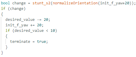
what I implemented is the following changes to my rotary_flag section:
Basically, what this does is it uses the localization PID control but
only asks it to rotate 20 degrees at a time before moving to the next step.
Once it has done "enough" 20 degree turns to reach the desired_value
then it will set terminate to true. These changes meant since my
car would only turn clockwise, I had to
change my output from determine_desired_orientation to be between
[0, 360] as opposed to [-180, 180]. This was fairly trivial
to do as I just added
360 whenever the value was negative for my input.
As a result, to turn -45 degrees, I had to actually turn 315 degrees.
While this was inefficient, it was necessary for my car to be
consistently precise and work with my IMU outputs.
Steps for Best Run Functionality
Localize at point
Use pose to get desired orientation
Use that to pass through to rotary_flag and turn it
the appropriate amount
Use precomputed results, to determine expected ToF
measurements for both sensors and continue calling linear_flag
until roughly in the desired range for one of them. Chose which
ToF to use to determine distance based on closeness to wall
as the closer one to a wall would be have more accurate readings.
This means as one moves away from the initial point it would use
the back ToF sensor since it would have more accurate readings.
Reach next waypoint and repeat
Some exceptions to the above order was
not localizing at the final point and at the
6th waypoint. In addition, the values passed
to the linear_flag function scaled and were
generally larger for waypoints that were further
apart until within a certain closeness of the point.
This means the last few waypoint motions had higher
initial inputs.
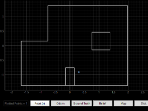
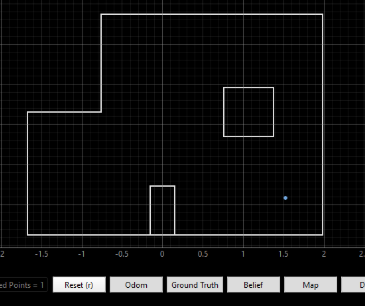
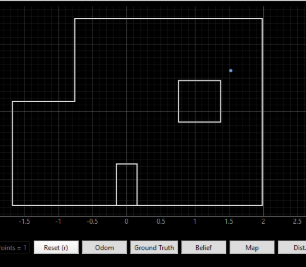
The Best Run
Belief Data
While I didn't end up screen recording the whole time,
I took screenshots of the localizations and recorded the output
data in regards to the belief and probability. I share it below.
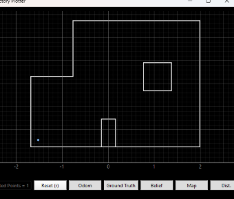
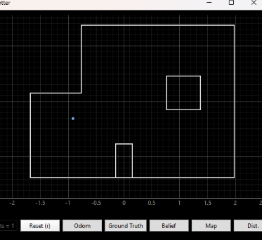
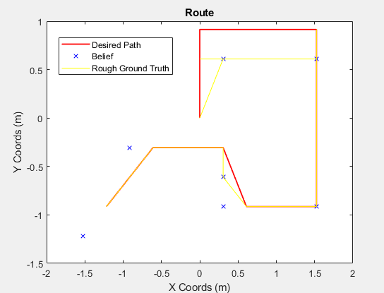
This is a rough map of a comparison of the localizations to the desired path
to the estimated ground truth by watching the video. Generally the localizations
are pretty close and the route is roughly followed. Some points were reached but then
when rotating for the localization it came off the waypoint etc. This is because
I was having battery issues so I bumped up the PWM signal to make it move faster
but it wasn't fully tuned for that situation. Overall, the route is followed
generally pretty well.
Room for Improvement
First of all, with more time I would have liked
to be able to figure out how to fix the incorrect sensor
readings I was getting to be able to more accurately
turn the robot and move it. Instead I ended up implementing
much more rudimentary controls just to get it to work
as intended consistently even though it was much slower
and not as clean or efficient as I would've liked.
Furthermore, the workflow wasn't fully
automated. I had to copy the belief state output by my
localization to run it through the functions shared
and then after that I had to pass those values to my
car over bluetooth. So while this wasn't fully automated
it could easily be implemented. With more time
complete automation of this workflow
would be the next goal.